Monday 9 May 2022

Updated 8 years on

 8 years on and 40,000 km travelled.

The motor remains strong though I have had to modify the coupling between gear box and motor after about 30,000 km.

Essentially, the Lovejoy coupling wore away and gave up. I replaced this with a cut down clutch plate


This is the worn out segment on the motor and gearbox (below).


Since then the DC/DC converter also gave up. The original was from USA and was a RV compromise.


 I have now replaced this with a Chennic DC-DC converter with no issues. However allied to this I have also updated the 12v battery . I previosuly had a AGM battery which proved to be a mistake. as it cant take over charging. Now back to  "normal" rideon mower battery and have had no issues in 2 years with that.

Lastly the main battery charger also gave up. Originnaly this was a TC Charger 144v from 240v AC. 8 Amp out.


This charger is no longer available and coincidentally another EV constructor locally to me, who had similar 144v setup, his TC charger similarly after 8 years broke down, though he has had his repaired. I opted to purchase a replacement from EVCOMPONENTS in China and resisted overtures for options to my selected ELCON Charger - Charge Enabled. This took some 4 months to be delivered but works excellently. 

Thursday 24 April 2014

Finished at Last

24 April 2013 - Finished at last
 On 17 March finally put it all together and ran the car  - albeit still on the jack stands. Thanks to Eric from AEVA who helped put the wiring together & provided me with circuitry to both make the heater work properly  , but also fabricated a dual diode & inductor on DC-DC charger, to prevent reverse draw from 12v battery to main pack.
Subsequent to then I had to completely pull down the dash again to get the ceramic heather out as there was smoke when I turned the heater on.
Eventually I removed all of the high temp silicone ( good as gasket in ICE engines but not so good in this situation) , and replace with Clipsal's fire proof mastic . Not as good a material to hold things in , but doesn't smoke!
Lastly I couldn't get the after market tacho to work on the NPN sensor that was attached to the shaft of the electric motor. Once more Eric to rescue with a resistor to act as a "pull down" resistance.

Stickers placed all over the place & Perspex guards fabricated to prevent unwanted shorting.
Runs great, though road noise m(whirring etc) is a distraction and hopefully will quieten down.  Also the AM side of the radio gets a lot of electrical interference. May have to come up with some form of shielding to improve that.

re-doing the heater


The circuitry to prevent back draw from 12v battery


Saturday 22 February 2014

Electronic Hardware Mounted

23 Feb 2014 - Hardware basically all connected and thanks to Eric, who noticed I had the connections for pre-charge on the contactor backwards, all the rest appears correct.
All the bits seem to be there.
Also completed a splash guard today.


 Some other pics of work as it progressed to today
 BMS LED & Controller LED's mounted in side the dash

LED s to the left of regular telltales in dash
Half way through wiring connectors. Looks good here but had a disaster near end as arced across the torque wrench and wrote that off! The following two images show the spark damage to back of driver's seat & the headlining.


Wiring batteries


N


Sunday 29 December 2013

Sunday 29 December
I have now 3 weeks off work so some progress should be very possible.
Since last post I have hosted a gathering of the AEVA Adelaide members at my home for a Saturday BBQ & general "Gasbagging" about things EV-wise. About 22 attended which was a pretty good rollup. Not to waste the occasion I obtained  a number of handy suggestions , though these wont be visible, they are useful in the  wiring up situation.
This shows the positive HT feed now with lugs to attach to the emergency switch ( that's it top right of picture) mounted in the centre console

You  can see that the glove box is still out , and so is the rest of the dash. I have yet to mount an LED that will feed from EVBMS from Ian Hooper in WA. Plus I am still perplexed over wiring into the heater fan circuit as part of the fail-safe measures for the demister. So that is why the glove box is still out, as it covers the wiring etc. for the fan motor.

Here is the console with the emergency switch and provision for the JLD404AH Intelligent Meter.
 

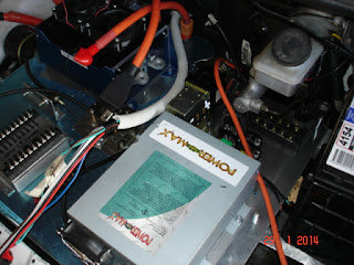
The two shots above are looking at the mounting box for the circuit breaker switch on left side of the grey box ( which will eventually have a cover). To the right is the 144v battery charger.
The feeds that  pass out to the underside of the car can be seen, as can the mounting bolts  that hold down the battery frame. These mount directly onto the seat belt mounts and ought to provide conformation to Aust. design standards for mounts.
The grey box also contains the 75mv shunt for the JLD404AH meter. The additional fuse is for 144v Neg. feed back to the meter as well. 


Underside of car looking forward.
 

Mounting all 45 batteries in the frame . Used SS banding in 3 sets of 15 batteries.
Then, also there is a 25mm flat passing between the banks terminating on a 1/4"thread. That then passes through part of the frame , to additionally lock in the banks. Finally there are 8 hold-downs on top that will be the final method of locking in the banks into the frame.


Progress with mounting the electrical hardware. Still mind bending!!!!!!
 
Progress also with the BMS wiring and battery interconnectors. 
 

Sunday 17 November 2013

Further progress


Inside the car - 240v conduit


How it looks with the caravan type socket in place of the petrol filler cap

Battery charger in position and to the right of frame is the 240v conduit & cable
Inside the car - these are the two glands for the Positive 144v cabling to the Emergency Stop switch
In engine bay  - this is the positive 144v cable and orange conduit coming from the underside of the car.
 Still have to pass the negative conduit & cable under the car from the battery pack.
 

Saturday 16 November 2013

Half shaft issues

Right side - 1/2 shaft in after modifying the motor support ( hidden)
Left side before CV & 1/2 shaft returned - at upper left is back side of gear box mount  filled with polyrethane
Right side  - from under car . The mounting plate had to be ground back slightly . Seems the engineer did not account for the fact that the CV steps out and get a little larger. All good now.
All good now.
Giving the gearbox new oil ! This is basically the end of the mechanical side.


Here is the engine bay again


2 months further on: hardly any progress

Battery frame & bits to go for galvanising


Battery frame


Motor hanging mount at top. Torque support nearest
After quite some time (2 months) , I figure it was time to update this blog.
First  piece of action was to get all the  welded bits etc. galvanised , both for the protection this will give but also from an aesthetic point of view.


after passivation
Here are the bits returned in gold passivation - Nice eh?
I got extra pieces of randon steel done as well - You never know!
 Note the motor support  - problems came later when I couldn't get the left side 1/2 shaft past this! Bugger!
 
 Battery  box - inside the  "runners" I have laid a strip of closed cell foam on the base  - the full length (20mm wide) and at each end.  


Mounted basically where the rear seats would have been. I also obtained some floor matting from a wrecker. This has been glued to the bare floor again , where the back seat was .
 
And here is what it might look more like once batteries are mounted.
 
 
The 20 mm closed cell foam is in the bottom of the guides (grey colour)